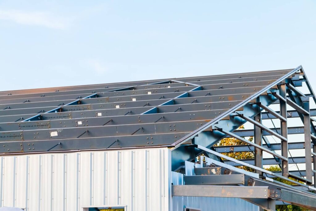
Parts of Metal Roof Systems
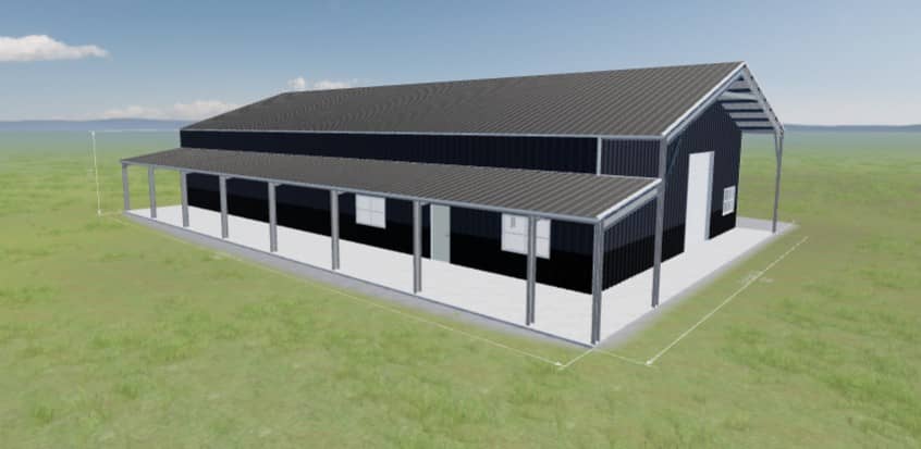
Understanding the anatomy of a metal roof systems is critical for anyone comparing metal building options, planning a project, or trying to make sense of engineering drawings. Every component; from the ridge and peak at the top of the structure to the eave height and knee inside, plays a specific role in how the building carries loads, sheds water, and creates usable interior space. Elements like purlins, BC runners, and wall plates tie the system together, while exterior features such as the rake, overhang, and roof slope shape both performance and appearance. Even the choice of roofing (whether standing seam or screw‑down) depends on how these components interact.
This guide breaks down each of these terms in clear, practical language so you can understand what they mean, where they’re located, and why they matter in a metal‑building design. Continue reading for straightforward definitions and descriptions of every major roof component, giving you the confidence to interpret plans, compare building systems, and make informed decisions about your project.

Jump to Subject
Clear Span
A clear span is simply how wide a building can be from one side to the other without needing any interior columns. Think of it as the amount of open floor space you get under the roof without anything in the way. When a building has a larger clear span, you end up with a wide, open interior that’s perfect for workshops, storage, vehicle bays, or commercial use because nothing interrupts the usable space.
But there’s a tradeoff: The wider the clear span, the stronger and heavier the structural frame must be to support the roof without help from interior supports. Stronger frames mean more steel, more engineering, and therefore a higher overall building cost. So clear span affects both the functionality of the space and the price of the structure.
Eave Height
Eave height is simply how tall the building is at the point where the roof meets the sidewall. If you stand next to the building and look at the lowest edge of the roof (the horizontal line where the wall stops and the roof begins) that height from the ground up is the eave height.
This measurement does more than describe the building’s exterior. It also controls how much usable vertical space you have inside. A higher eave height gives you more clearance for things like lifts, tall equipment, RVs, stacked storage, or even a mezzanine level. A lower eave height limits what can fit inside and shapes how the interior can be used.
Because of that, eave height affects both the building’s appearance and its functionality. It determines the overall profile from the outside and the working space available on the inside.
Gable Roof
A gable roof is one of the simplest roof shapes to understand because it’s built from two sloping sides that rise and meet at the top. Where those two slopes connect, you get the ridge; the highest horizontal line of the roof. When you look at the building from either end, those two slopes form a clean triangular shape, which is the classic “gable” profile.
This design isn’t just common because it looks familiar. Its straightforward geometry naturally sheds water and snow, which helps protect the building and reduces long‑term maintenance. The shape also creates a clean, functional appearance that works well for everything from homes to metal buildings and commercial structures.
Insulation System
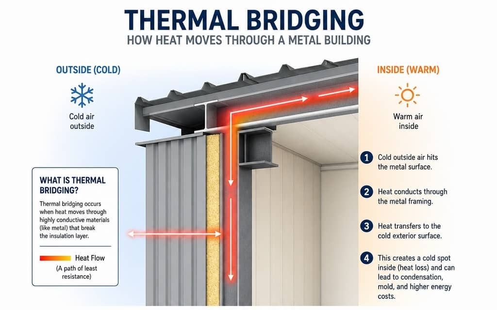
A roof insulation system is the collection of materials placed inside the roof structure to slow down the movement of heat. In hot weather, insulation helps keep heat out; in cold weather, it helps keep warmth in. By controlling how easily heat passes through the roof, insulation makes the building more energy‑efficient and reduces the workload on heating and cooling systems.
Insulation also plays a major role in controlling condensation. When warm, moist air inside the building meets a cold roof surface, moisture can form and lead to dripping, mold, or corrosion. A properly designed insulation system keeps those surfaces warmer and prevents that moisture from forming in the first place.
The result is a building that stays more comfortable year‑round, uses less energy, and avoids the long‑term problems caused by uncontrolled temperature swings and moisture.
Knee
The knee is simply the lowest point inside the building where the roof starts sloping upward. If you stand along the inside wall and look up, you’ll see the roof angle begin-that spot is the knee. It’s the point where the vertical wall ends and the angled roof begins.
This matters because the knee effectively sets the limit for how tall objects can be along the edges of the building. A lower knee height reduces usable wall space and can restrict where you place shelving, equipment, or storage. A higher knee height gives you more functional room before the roof starts cutting into the interior space.
In short, the knee determines how much of the interior feels open and usable, and it directly influences how the space can be arranged or outfitted.
Overhang
The overhang is simply the part of the roof that sticks out past the exterior wall. If you stand next to the building and look up, you’ll see the roof extending outward beyond the siding, that extended portion is the overhang.
That extra bit of roof plays an important protective role. By projecting outward, it helps keep rainwater away from the walls, reduces how much sun hits the building, and limits weather‑related wear. At the same time, the overhang influences how the building looks. Longer or shorter overhangs change the proportions of the roofline and can make the structure appear more balanced, modern, or traditional depending on the design.
So even though it seems like a small detail, the overhang affects both how well the building handles the elements and how the building looks from the outside.
Peak
The peak is simply the very highest point of the roof. It’s the topmost spot where the two sloping sides of the roof come together, which is usually right along the ridge line. If you imagine tracing the roof upward from either side, the point where those slopes meet is the peak.
Because it’s the highest point, the peak defines the overall shape and silhouette of the building. It sets the roofline’s upper boundary and plays a big role in how tall, steep, or balanced the structure appears from the outside. In short, the peak is the roof’s topmost reference point and a key part of its visual identity.
Purlin
A purlin is a horizontal beam that runs across the roof, sitting on top of the main frames or trusses. Its job is to hold up the roof panels; the metal sheets that form the finished roof surface. Instead of attaching those panels directly to the main structural frames, purlins create a lighter, more efficient support system in between.
Because purlins carry the weight of the roof panels and transfer that load back to the main structure, they allow the primary frames to be spaced farther apart. That means fewer heavy frames are needed, which reduces material costs and speeds up construction.
Rake
A rake is easy to picture once you imagine standing at the end of a gable‑style building and looking up at the roofline.
The rake is the sloped edge of the roof, the line that runs upward from the eave (the lower edge of the roof) all the way to the ridge (the top). It outlines the triangular shape of a gable end and gives the roof its distinctive profile.
Because it’s an exposed edge, the rake also plays a role in protecting the building from weather. Proper trim and detailing along the rake help keep wind‑driven rain from getting behind the roof panels and improve the durability of the structure. At the same time, the rake contributes to the building’s overall appearance, influencing how sharp, clean, or finished the roofline looks.
Ridge
The ridge is simply the long, horizontal line at the very top of the roof; the place where the two sloping sides meet. If you imagine tracing each roof slope upward, the point where they come together forms the ridge, which also creates the roof’s highest line or peak.
Because it sits at the top of the structure, the ridge plays an important role in how the roof is shaped and how it functions. It defines the overall roof geometry, and it’s also the location where many buildings incorporate ridge vents to let warm air escape. That makes the ridge a key reference point for both the roof’s appearance and its ventilation performance.
Roof Extension
A roof extension is any part of the roof that stretches out beyond the main walls of the building. Instead of the roof ending exactly at the exterior wall, it continues outward to create extra coverage. This projection can be small (like a modest eave) or much larger, depending on the design.
That extra reach serves several purposes. Functionally, it helps keep rainwater farther away from the walls and foundation, reducing long‑term moisture issues. It also provides shade and shelter, which can make entryways, walkways, or outdoor work areas more comfortable and protected. Visually, a roof extension adds shape and depth to the building, giving it a more intentional and balanced architectural look.
Roof Panel
A roof panel is the metal sheet that forms the outer skin of the roof, attached directly to the purlins beneath it. These panels create the finished surface you see from the outside and act as the building’s first line of defense against weather. Because they handle constant exposure to sun, rain, wind, and temperature changes, roof panels are engineered for long‑term durability, strength, and resistance to corrosion.
In simple terms, the roof panels are what keep the elements out. They seal the structure, shed water, and protect everything inside while giving the building its clean, finished appearance.
Roof Slope/Pitch
A roof slope, or pitch, is a way of describing how steep the roof is. It tells you how much the roof rises vertically over a fixed horizontal distance. So when you see a ratio like 1:12 or 6:12, it means the roof rises 1 inch or 6 inches for every 12 inches of horizontal run. The bigger the first number, the steeper the roof.
That slope affects several important parts of the building. A steeper pitch sheds water and snow more quickly, which can improve durability in harsh climates. It also changes the overall look of the building, making the roofline appear flatter or more pronounced. And because different roofing systems are designed for different slopes, the pitch determines which types of panels or assemblies can be used safely and effectively.
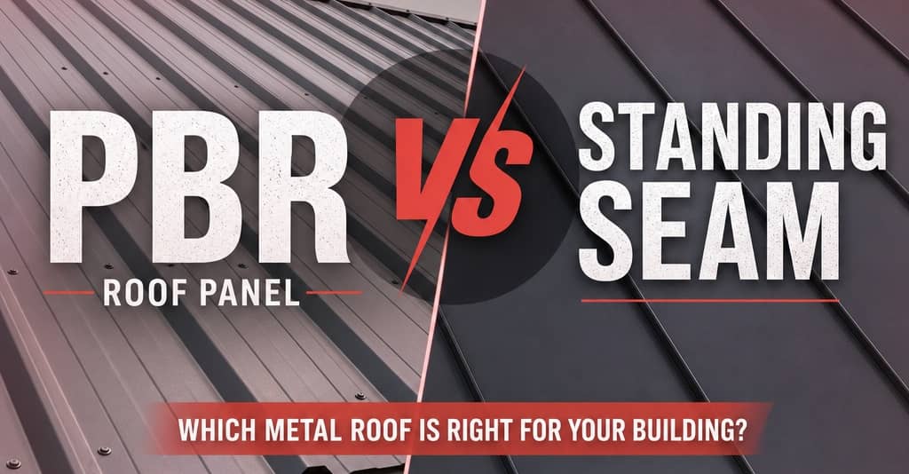
Screw Down Roof
In a screw‑down system, each roof panel is laid over the framing and secured with exposed fasteners that penetrate the metal and hold it firmly in place. Those screws go through the panel and into the purlins or framing below, creating a straightforward, no‑nonsense installation. Because the fastening method is simple and doesn’t require specialized equipment, screw‑down roofs are more affordable than concealed‑fastener systems.
This makes them a popular choice for utility buildings, barns, shops, garages, and other structures where cost efficiency and quick installation matter more than long‑term expansion control or premium aesthetics. The tradeoff is that the exposed screws and washers will eventually need maintenance or replacement as the building moves and the washers age.
Standing Seam Roof
In a standing seam system, each roof panel has raised vertical seams along the edges. Instead of driving screws through the surface of the metal, the panels are attached with hidden clips or concealed fasteners underneath. The raised seams then lock together over those clips, creating a continuous, watertight connection with no exposed screws on the roof surface.
Because nothing penetrates the top of the panel, the system is far better at keeping out water, handling thermal expansion, and resisting long‑term wear. With no exposed fasteners to loosen, rust, or require periodic tightening, maintenance needs drop dramatically.
The result is a roof that’s cleaner in appearance, more durable, and more weather‑resistant than screw‑down systems; making it a preferred choice for higher‑end buildings, barndominiums, and any project where longevity and performance matter.
What's Next?
Ready to discuss your metal building project? ROI Metal Buildings delivers cost-effective structural solutions that can save you 20-30% compared to traditional metal building systems. Our expert team specializes in comprehensive truss design, from clear span to purlin, ensuring maximum efficiency and structural integrity.
Contact ROI Metal Buildings today:
- Get a detailed cost analysis
- Receive custom truss specifications
- Start saving on your construction project
Call 865-855-9095 or contact us now to request your free quote and consultation.